
CNC Machining Surface Finish: How to Define Critical Surfaces Before Production


CNC machining surface finish can directly affect how a component fits, seals, moves, or contacts another part. Consider an aluminum housing with visible milling marks on its exterior and a precision-machined sealing face. Both surfaces may look similar, but their functional requirements can be very different.
For OEM buyers, the challenge is not simply requesting a smooth finish. It is identifying which surfaces require control, defining measurable acceptance criteria, and ensuring that the manufacturer and customer evaluate the finished part under the same conditions.
How CNC Machining Surface Finish Requirements Become an Inspection Plan
A technical drawing should distinguish critical functional surfaces from general machined areas. Bearing seats, sealing faces, sliding surfaces, and precision mating features may require specific surface texture conditions. Other areas may only need to be free from harmful burrs or visible defects. Applying unnecessarily strict surface requirements across an entire component can increase machining time and inspection cost without improving its performance.
Surface Roughness and Waviness Are Different
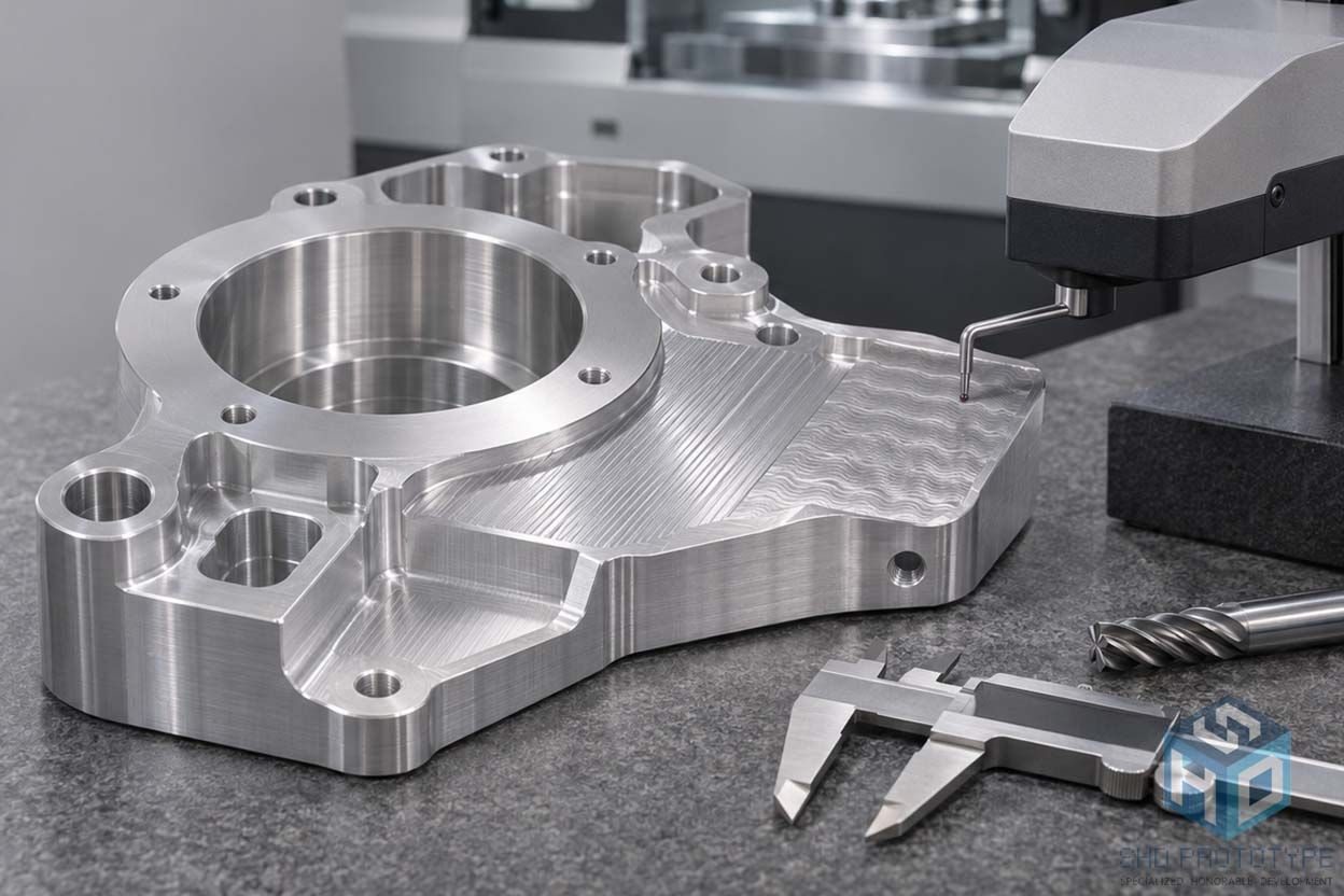
A CNC surface roughness specification commonly uses parameters such as Ra or Rz to describe selected characteristics of a surface profile. However, roughness is not the same as waviness. Roughness describes relatively fine surface irregularities, while waviness represents longer-spaced variations. A surface may satisfy its specified roughness limit yet still contain undesirable periodic patterns or larger-scale deviations. This distinction matters when machining broad sealing faces, precision sliding surfaces, or other areas where surface contact is important.
The applicable measurement standard and evaluation conditions should therefore be defined rather than relying on a roughness number alone.
Chatter Marks Require More Than Visual Inspection
CNC machining chatter marks may appear as repeated waves or irregular patterns across a machined surface. They can result from machining vibration involving the cutting tool, workpiece, fixture, or machine structure.
Long tool overhang, insufficient workpiece support, tool wear, and unsuitable cutting conditions may contribute to unstable machining. However, visible tool paths do not automatically indicate chatter or a defective part. Regular feed marks can be a normal result of machining.
If surface appearance or vibration-related patterns are functionally important, the drawing should define the appropriate measurable requirements or agreed visual acceptance criteria.
Measurement Location and Direction Matter
Precision machining surface finish inspection requires more than recording a single measurement. A surface profilometer measures texture along a defined profile. Results can be influenced by the selected measurement location, direction, filtering, and evaluation length. When a surface has a clear machining lay, measurement is commonly performed across the dominant tool marks unless the applicable specification requires another direction.
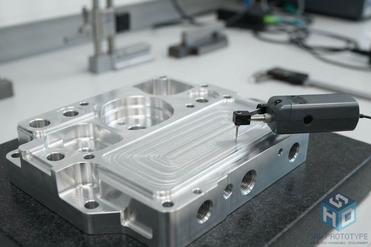
For parts containing several functional surfaces, buyers should identify the measurement areas rather than allowing inspection at an arbitrary convenient location.
Define the Final Inspection Condition
Some CNC-machined components undergo anodizing, plating, polishing, blasting, or other finishing operations. These processes may change the surface texture or affect the appearance of machining marks.
The customer and manufacturer should therefore agree on whether the specified finish applies to the as-machined surface or the final treated component. Before approving production, a useful surface-finish agreement should identify:
- Critical surface locations on the drawing
- Required roughness or other texture parameters
- Applicable measurement standard
- Measurement direction and evaluation conditions
- Relevant waviness or visual appearance requirements
- Inspection stage and sampling expectations
Where appropriate, an approved first-piece sample, representative surface photographs, and measurement records can provide useful references for later production batches.
Conclusion
CNC machining surface finish should be treated as a functional manufacturing requirement rather than a general request for smooth-looking parts. Clear surface identification, appropriate texture parameters, controlled machining conditions, and agreed inspection methods help reduce uncertainty between engineering, production, and procurement teams.
Defining these requirements before quoting or machining is often more effective than resolving surface-quality disagreements after delivery.
Surface Finish Planning with SHD PROTOTYPE
SHD PROTOTYPE supports custom CNC machining projects based on customer drawings, material specifications, functional surfaces, dimensional requirements, and production quantities. For components with demanding surface requirements, early discussion of critical areas, machining access, finishing operations, and inspection expectations can help establish a practical manufacturing route.
Clear specifications also support more consistent communication when prototype components progress toward repeat production.